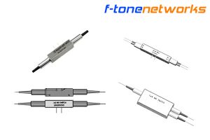
Характеристики продукта
● Низкие вносимые потери
● Широкий диапазон длин волн
● Низкий уровень перекрестных помех
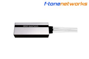
● Компактная конструкция
● Высокая скорость переключения
Области применения
● Пассивные оптические сети
● Системы оптической защиты
● Измерительные системы
● Мониторинг сетей
Технические характеристики.
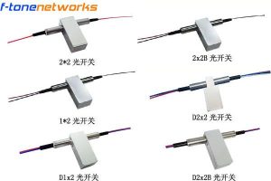
| Parameters | unit | FT-98-OSW-D2x2B | |
| Operating wavelength | nm | SM:1260~1620 | MM:850±40 |
| Test wavelength | nm | 1310 / 1550 | 850 |
| Insertion loss (IL) | dB | ≤0.8(典型值:0.6 ) | |
| Wavelength-dependent loss (WDL) | dB | ≤0.25 | |
| Temperature-dependent loss (TDL) | dB | ≤0.2 | |
| Polarisation-dependent loss(PDL) | dB | ≤0.05 | |
| Return loss(RL) | dB | SM≥50 ,MM≥30 | |
| crosstalk(CT) | dB | SM≥55 ,MM≥35 | |
| Repeatability | dB | ≤±0.02 | |
| Switching speed | ms | ≤8 | |
| Number of switches | times | ≥10 million | |
| Operating voltage | V | 3.0 or 5.0 | |
| optical power handling | mw | ≤500 | |
| Operating temperature | ℃ | -5~+70 | |
| Storage temperature | ℃ | -40~+85 | |
| Operating humidity | ℃ | 5~95 | |
| Package dimensions | mm | L27xW12xH8.2 | |
| Notes: 1. All parameters were tested under room temperature conditions. 2. All parameters exclude connector insertion loss; each connector adds 0.3 dB of loss. | |||
Определение выводов драйвера
| Type | Status | Light path | Electric drive | Status indicator | ||||||
| D2x2B | Pin 1 | Pin 5 | Pin 6 | Pin 10 | Pin 2-3 | Pin 3-4 | Pin 7-8 | Pin 8-9 | ||
| Self-locking | A | P1-P3‵ | – | – | GND | V+ | Close | Open | Open | Close |
| P2-P4‵ | ||||||||||
| B | P1-P1‵,P2-P2‵ | V+ | GND | – | – | Open | Close | Close | Open | |
| P3-P3‵,P4-P4‵ | ||||||||||
| Non-self-locking | A | P1-P3‵ | – | – | – | Close | Open | Open | Close | |
| P2-P4‵ | ||||||||||
| B | P1-P1‵,P2-P2‵ | V+ | – | – | GND | Open | Close | Close | Open | |
| P3-P3‵,P4-P4‵ | ||||||||||
Параметры электронного управления
| Type | voltage | current | resistor |
| 5V Self-locking | 4.5~5.5V | 36~44mA | 125Ω |
| 5V Non-self-locking | 4.5~5.5V | 26~32mA | 175Ω |
| 3V Self-locking | 2.7~3.3V | 54~66mA | 50Ω |
| 3V Non-self-locking | 2.7~3.3V | 39~47mA | 70Ω |
Схема светового пути

Схема размеров модуля

Примечание: Для электрических разъемов модулей M3, M4 и M5 используется разъем MOLEX 87833-1620; в качестве разъема для клиентов рекомендуется использовать MOLEX 87568-1694.
Информация о заказе FT-98-OSW-D1x2-A-B-C-D-E-F
| A | B | C | D | E | F |
| Test wavelength | Switch type | Fiber type | Fiber diameter | Fiber length | Connector type |
| 850: 850nm | 3L: Self-locking | SM: Single-mode 9/125 | 025: Φ0.25mm | 05: 0.5m | 00: None |
| 1310: 1310nm | 3N: Non-self-locking | M1: Multi-mode 50/125 | 09: Φ0.9mm | 10: 1.0m | FP: FC/UPC |
| 1550: 1550nm | 5L: Self-locking | M2: Multi-mode 62.5/125 | X: Other | 15: 1.5m | FA: FC/APC |
| D: 1310/1550nm | 5N: Non-self-locking | X: Other | X: Other | SP: SC/UPC | |
| X: Other | SA: SC/APC | ||||
| LP: LC/UPC | |||||
| LA: LC/APC | |||||
| X: Other |
Важное уведомление:
Performance figures, data and any illustrative material provided in this data sheet are typical and must be specifically confirmed in writing by F-tone Networks before they are applicable to any particular order or contract. In accordance with the F-tone Networks policy of continuous improvement specifications may change without notice.The publication of information in this data sheet does not imply freedom from patent or other protective rights of F-tone Networks or other. Further details are available from any F-tone Networks sales representative.
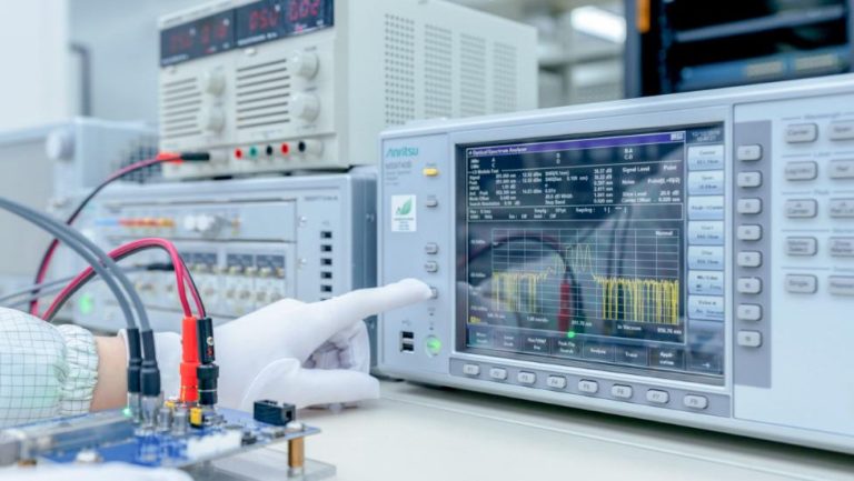
Power and Wavelength Testing
Test the signal delivering strength and wavelength, to ensure the signal decoding capacity of the receiver, and the wavelength remains consistent from the transmitter to the receiver.
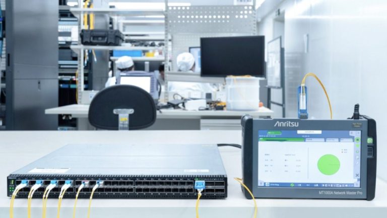
Traffic Testing
Test the bit error rate and packet loss rate, to make them meet the corresponding standards and ensure the performance of transceivers.
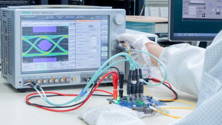
Optical Performance Testing
Test the transceivers’ eye diagram situation, receiving sensitivity, extinction ratio, wavelength, light-emitting, light-receiving, current and voltage, to ensure the signal quality, stability and reliability of the transmission.
End Face Testing
Check the end face of the transceivers and keep them clean for more stable data transmission, better performance, and durability.