Характеристики продукта
● Низкие вносимые потери
● Широкий диапазон длин волн
● Низкий уровень перекрестных помех
● Высокая стабильность и надежность
● Управление через параллельный интерфейс (уровень TTL)
● Модульная конструкция
Области применения
● Лабораторные исследования и разработки
● Мониторинг систем
● Настройка OADM
● Городские сети
● Многоканальный мониторинг оптических сигналов
● Волоконно-оптические датчики
● Удаленные оптоволоконные линии
● Системы мониторинга
| Model | FT-98-FSW-1× N | ||
| Wavelength range nm | 800~1100(MM) | 1400~1700( MM ) | 1250~1650( SM ) |
| Test wavelength nm | 850/980 | 1550 | 1310/1490/1550/1625 |
| Insertion loss dB | Typ:0.6 Max:1.0 | Typ:0.6 Max:1.0 | Typ:0.8 Max:1.3 |
| Return loss dB | SM≥50、MM≥30 | ||
| Channel cross talk dB | SM≥55、MM≥50 | ||
| Polarization-dependent loss dB | ≤0.05 | ||
| Wavelength-dependent loss dB | ≤0.25 | ||
| Temperature-related losses dB | ≤0.25 | ||
| Repeatability dB | ≤±0.02 | ||
| Operating voltage V | +5 ( DC ) | ||
| Number of uses | ≥107 | ||
| Switchover time ms | ≤10(相邻信道切换) | ||
| Transmitted optical power mW | ≤500 | ||
| Operating temperature℃ | -20~ +70 | ||
| Storage temperature℃ | -40~ +85 | ||
Pin Definition
DB9 (TTL level):
| Pin number | Signal direction, type (In/Out/Power) | Pin Definition | Function Description |
| 1 | In | D0 | Data bits. D3–D0 represent a binary number, with D3 as the most significant bit and D0 as the least significant bit. The 4-bit data can control up to 16 optical switch channels. Specifically, 0000b corresponds to channel 1, and 1111b corresponds to channel 16. When using this feature, transmit data based on the actual number of optical switch channels. |
| 2 | In | D1 | |
| 3 | In | D2 | |
| 4 | In | D3 | |
| 5 | In | /Reset | A low level resets to channel 0; a high level enables the data bit. |
| 6 | Out | /Ready | Low level: ready to reset or receive data. |
| 7 | Out | Error | A high level indicates an operational error in the optical module. |
| 8 | Power | GND | Ground Wire |
| 9 | Power | DC 5V | DC 5V ,1.0A Mains power supply |
DB15 (TTL level):
| Pin number | Signal direction, type (In/Out/Power) | Pin Definition | Function Description |
| 2 | In | D0 | Data bits D5 to D0 represent a binary number, with D5 being the most significant bit and D0 the least significant bit. A 6-bit binary number can control up to 64 optical switch channels. Specifically, 000000b corresponds to channel 1, and 111111b corresponds to channel 64. When using this system, data should be transmitted according to the actual number of optical channels in the optical switch. |
| 3 | In | D1 | |
| 4 | In | D2 | |
| 5 | In | D3 | |
| 6 | In | D4 | |
| 10 | In | D5 | |
| 11 | In | /Reset | Low-level reset; data bits are active at high level. |
| 7 | Out | /Ready | Low level: ready to reset or receive data. |
| 8 | Out | Error | A high level indicates that an error has occurred. |
| 15 | Power | 5V | Power supplies for digital circuits |
| 12 | Power | 5V | Motor power supply |
| 1 ,9 | Power | Ground | Common ground |
| 13 ,14 | Not connected | ||
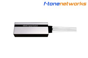
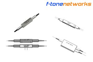
Габаритные размеры Д×Ш×В (мм)
1XN (2<N≤16) Type A:120×40×32

1XN (2<N≤16) Type B: 135×60×35

1XN (2<N≤16) Type C: 135×40×32

1 × N( 17≤N≤32 ) Type A:120×50×50

1 × N( 17≤N≤32 ) Type B: 114x110x32

1 × N( 17≤N≤32 ) Type C: 150x76x60

1 × N( 33≤N≤64 ):150 ×90 ×78

1 × N( 65≤N≤128 ): 172×150×78

Информация о заказе:FT-98-FSW-1xN-A-B-C-D-E-F
| N | A | B | C | D | E |
| Number of channels | Fiber specifications | Operating wavelength | Outer diameter of the optical fiber | Fiber length (including connectors) | connector |
| 1 ~ 128 | SM: SM, 9/125M5: MM, 50/125M6: MM, 62.5/125 | 850: 850nm1310: 1310nm1550: 1550nm1310/1550:1310/1550nm X:其它 | 90: 900um20: 2.0mm30: 3.0mmX: Others | 05: 0.5m±5cm10: 1.0m±5cm15: 1.5m±5cmX: Others | OO:NoneFP: FC/PCFA: FC/APC SP: SC/PCSA: SC/APC LP: LC/PCLA: LC/APC X: Others |
| F(Size code) | Compatible models | Dimensions( mm) |
| 1 | 1XN (2<N≤16) | Type A:120×40×32 |
| 2 | 1XN (2<N≤16) | Type B: 135×60×35 |
| 3 | 1XN (2<N≤16) | Type C: 135×40×32 |
| 4 | 1×N( 17≤N≤32 ) | Type A:120×50×50 |
| 5 | 1×N( 17≤N≤32 ) | Type B: 114x110x32 |
| 6 | 1×N( 17≤N≤32 ) | Type C: 150x76x60 |
| 7 | 1×N( 33≤N≤64 ) | 150×90×78 |
| 8 | 1×N( 65≤N≤128 ) | 172×150×78 |
Важное уведомление:
Performance figures, data and any illustrative material provided in this data sheet are typical and must be specifically confirmed in writing by F-tone Networks before they are applicable to any particular order or contract. In accordance with the F-tone Networks policy of continuous improvement specifications may change without notice.The publication of information in this data sheet does not imply freedom from patent or other protective rights of F-tone Networks or other. Further details are available from any F-tone Networks sales representative.
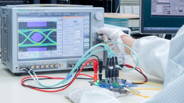
Power and Wavelength Testing
Test the signal delivering strength and wavelength, to ensure the signal decoding capacity of the receiver, and the wavelength remains consistent from the transmitter to the receiver.
Traffic Testing
Test the bit error rate and packet loss rate, to make them meet the corresponding standards and ensure the performance of transceivers.


Optical Performance Testing
Test the transceivers’ eye diagram situation, receiving sensitivity, extinction ratio, wavelength, light-emitting, light-receiving, current and voltage, to ensure the signal quality, stability and reliability of the transmission.
End Face Testing
Check the end face of the transceivers and keep them clean for more stable data transmission, better performance, and durability.